Reaktor Tutorials
Telephone Filter in Reaktor
In this tutorial, I’ll show how to make a simple macro to simulate a vintage telephone filter in Reaktor. This can be done completely in Primary, using some simple math and basic signal processing. This tutorial is based on a section in the book Digital Audio Effects, edited by Udo Zölzer. A download will be provided at the end for those who are interested.
This is an intermediate tutorial, assuming basic knowledge of filters and waveshapers. Appropriate links will be provided to get you up to speed along the way.
OVERVIEW
The basic structure of the vintage telephone simulation contains four elements: A pre-filter, distortion, added noise, and a post filter. Taken individually, each of these elements can be constructed with relative ease. Modern telephones, due to better quality components, can be modeled simply with the post filter, which is a bandpass. As such, they do not exactly make an exciting project on their own.
PRE-FILTER
The pre-filter has the structure of a comb filter. The transfer function is given by:
y = 0.9x(n) – 0.75x(n-11)
Where y is the output, x(n) is the input, and x(n-11) is the input delayed by 11 samples. This can be made pretty easily with a Single Delay module and some math:
DISTORTION
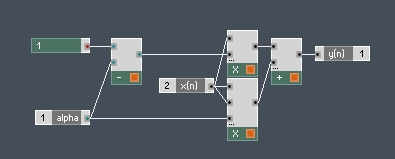
The distortion macro adds some grit and character to the sound. As it is based on a non-linear function, it might be a good idea to use oversampling, however, since we are processing voice signals, and the equation only adds second order harmonics, it is unlikely to cause much aliasing.
The equation for the distortion is given as:
y(n) = (1 − α)x(n) + αx2(n)
where x(n) is the input, y(n) is the output, and “α” is the amount of distortion. Again, this is easy to implement using simple arithmetic:
POST-FILTER
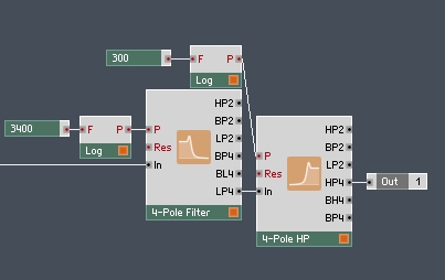
We’re going to skip right over the noise factor here, since all that is required in that section is a Noise Oscillator module with a very low amplitude being added to the signal directly after the distortion macro. The last element is also very simple – a bandpass filter allowing though frequencies between 400 Hz and 3400 Hz.
To make this, I’ll simply use a low pass and a high pass connected in serial:
The band pass ends up filtering our white noise (evenly distributed across the frequency spectrum) and making it colored noise instead.
CONCLUSION
This cool little project yields some pretty nifty results. You can download a basic ensemble using it here.
If you have any comments, questions, or suggestions, please post them below.


 YOUTUBE